

Safety valve, essential component in fluid regulation
1) Why a Safety Valve?
Under European Union law, any item of equipment or vessel that is under pressure that is sold and/or used within EU borders, must be protected in the event of overpressure by an EC certified safety device. Generally speaking, devices or organs must meet the requirements of the Pressure Equipment Directive (PED 2014/68 EU), no matter that certain markets or applications lay down their own, more stringent regulations, among them being the nuclear, aerospace and automotive industries. The Pressure Equipment Directive governs the whole supply chain from design to the assessment of materials, manufacturing processes, product inspections, testing and final recommendations on products in use and their maintenance.
2) What is a Safety Valve?
A safety valve is a device designed to protect equipment under pressure from exposure to overpressure, i.e. in excess of the maximum admissible. A safety valve is covered by the EU Pressure Equipment Directive 2014/68. ETNA Industrie safety valves are designed under calculation codes differentiated by target market, yet compliant to EU requirements. ETNA Industrie in the design of its safety valves, relies more generally on standards EN 13445-3 and ISO 4126.
3) What is the difference between a safety valve on the one hand, and a relief or adjustable flowrate valve, or a pressure limiting device on the other?
There is often confusion between the safety valve and valves more generally.
A saftey valve operates only in the event of emergency, unlike the valve which controls the passage of a fluid through it. The safety valve is designed to open only in the presence of an essentially non-recurrent condition, which is to be avoided as being potentially hazardous. Unlike a pressure regulation valve, which operates in response to recurrent conditions, a safety valve, if forced to open, should prompt inspection of the system it protects, in order to identify the causes of its opening.
Pressure regulating valves are not subject to the same regulations as safety valves. Their purpose is to ensure stability and control of valve inlet pressure. Valves open when pressure exceeds the desired value, or is liable temporarily to rise above a set value. Unlike the safety valve, valves are designed for repeated, even cyclical operation, and therefore to withstand fatigue. Their construction must optimize their performance over time and resist the wearing, scouring or similar conditions that affect fitness for purpose.
ETNA Industrie produces a range of such pressure-adjusting and pressure-limiting valves including a series that are manually adjustable. However, they should not be confused with safety valves.
4) How does a safety valvework?
Generally, a safety valve is fitted with a spring that automatically recloses the valve after opening as a result of overpressure. The safety valve is therefore standalone and self-acting in so far as the force to operate it is provided by the fluid whose pressure is controlled or more accurately, limited to a maximum pressure beyond which safety is compromised. Its primary purpose is detection of that excess pressure. The diagrams bellows illustrate this:
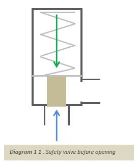
Diagram 1: The safety valve is normally closed and leak-tight. Pressure on the valve inlet (blue arrow), when it is below the set-point, exerts a force on the detection surface (blue arrow), which is less than the force exerted by the spring (green arrow). The disc is kept in place on the valve seat by the balance of forces for closure.
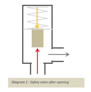
Diagram 2: Fluid inlet pressure (red arrow) is greater than or equal to the spring-loaded valve’s closing pressure. The spring no longer exerts sufficient force to keep the disc on the valve seat. The safety valve opens and excess pressure is relieved (grey arrow).
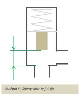
Diagram 3: When the safety valve is completely open it is said to be at full lift. The pressure at this point can rise to 110% of the initial valve opening pressure (aka “set” pressure). This is known as “overpressure.” Maximum liquid release rate is attained when the point of maximum design overpressure is reached.
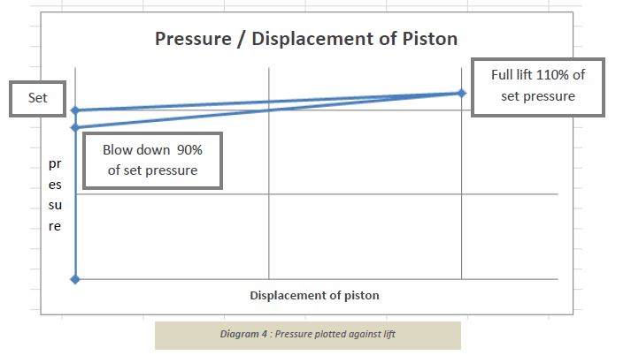
Diagram 4: illustrates the hysteresis effect (pressure drop after time lag), here plotted as the pressure gap between the set pressure on valve opening and the lower reseating pressure on reclosing (blow down).
Once the safety valve disc reaches full lift, the valve is open, thus releasing liquid whose pressure in the circuit is relieved. Pressure drop at inlet then allows the disc to fall back to the valve seat. ISO 4126 standard imposes limits on hysteresis or resetting values (Blow down). When the inlet pressure drops, the pressure of the spring is greater on the disc, which recloses and recreates the seal with the valve seat.
ETNA Industrie hysteresis values are on average – 10% of set pressure a considerably lower value that the -15% to -20% drop from set pressure of the ISO 4126-1 standard (variable by type of liquid). This is achieved by ETNA Industrie’s adoption advanced indirect action technology, which avoids undue pressure loss.
Indirect technology achieves this by operating somewhat differently. It redirects the liquid away from the disc to a pressure-sensitive diaphragm, piston or bellows in a detection chamber, depending on the design.
5) Indirect technology [ Spring / Guide / Inlet / Disc / Outlet ]
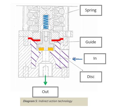
Diagram 5: illustrates an ETNA Industry indirect action safety valve in “reclosed” position. The valve is actuated by a pressure detection diaphragm and a stress limiter.
The valve design allows fluid to enter on the side (blue arrow), fill the pressure chamber (purple cross-hatch), and exert pressure on the red diaphragm whose surface area is proportional to and greater than the disc area in yellow. When pressure on the diaphragm is less than set pressure the disc remains pressed to the valve seat. The force limiter, however, reduces the closing force exerted on the disc, thereby protecting it from shearing or premature wear.
As inlet pressure rises to set point, it exerts sufficient force on the diaphragm to begin compressing the spring. But the disc with its piston and spring assembly is, because of the force limiter, not subjected to sufficient lifting force until the precise inlet set pressure is reached. The disk then lifts along with its assembly. The valve opens and excess pressure is relieved.
When the inlet pressure subsequently drops, the valve recloses as soon as the lower pressure level sought by design is reached, reversing the above.
6) Outstanding features of ETNA Industrie safety valves.
ETNA Industrie’s developments of this technology have further enhanced its performance:
- More precise pressure detection is achieved by increasing the area of the detection surface. ETNA Industrie valves operate to pressure tolerances of as little as +/- 3%, even at very low pressure, i.e. for set pressures of <100m bar
- Insensitivity to back-pressure: Given that force is equal to pressure multiplied by surface area (F=P.S), the greater surface area of the membrane means it is proportionally subject to greater force than the pressure on the disc surface, which applies irrespective of the value of the counter pressure.
- Optimized dimensions: Inlet and outlet diameters, relative to the nozzle diameter, are designed to such dimensions as achieve abatement of noise and vibration
- Reduced hysteresis: The indirectly actuated valve mechanism narrows the pressure gap between the set pressure required to open the valve, and the follow-on lower pressure that enables reseating.
Read more : The lexicon of the safety valve
Sandrine SELVARADJOU (Sales Department), Marine JUDENNE (Technical Department)
This entry was posted in Product, Produits and tagged safety valve on .
Become first to comment !